At this stage the model should be in ready-to-fly condition
with all of the systems in place.
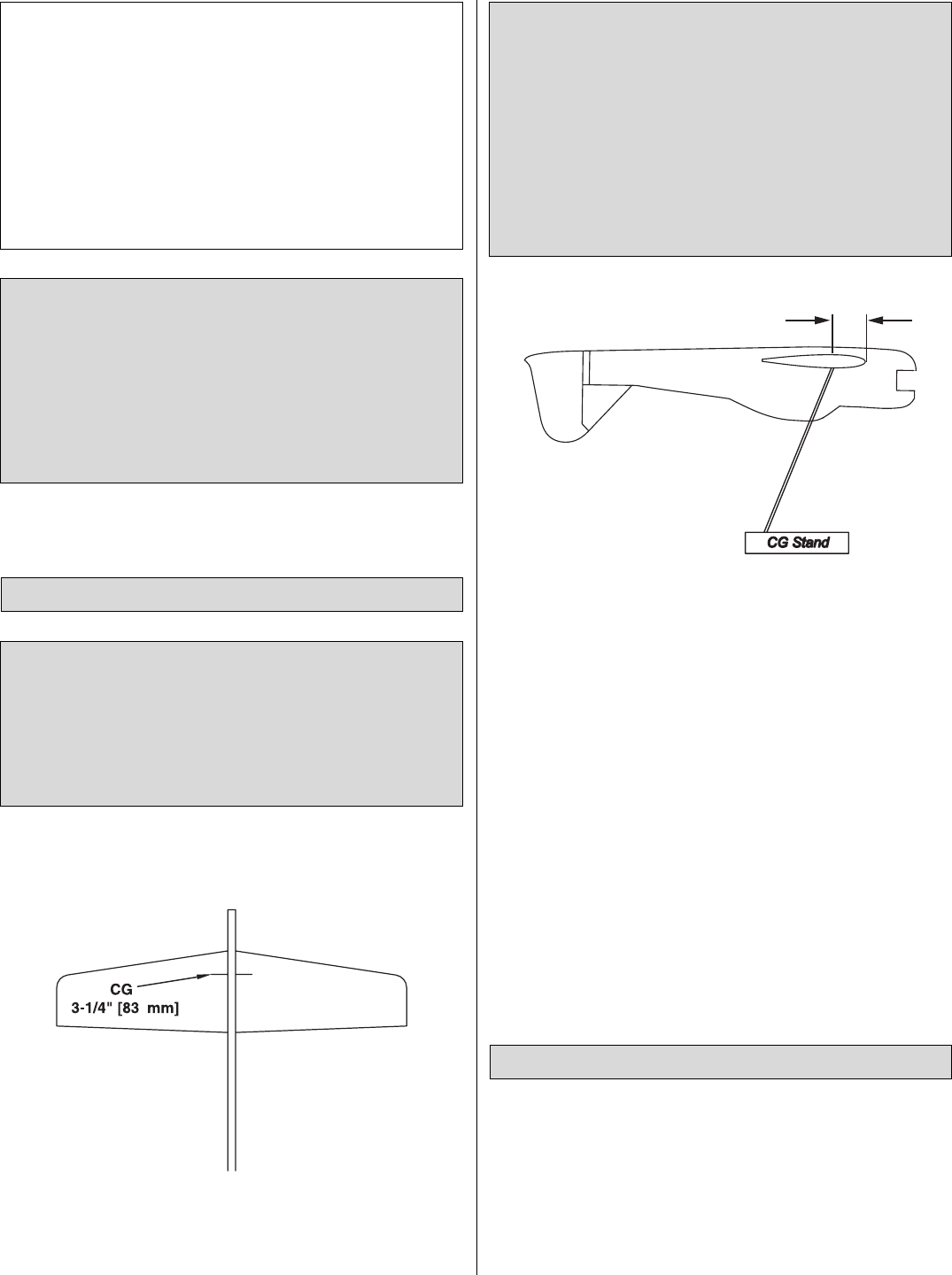
❏ 1. Use a felt-tip pen or 1/8" [3 mm]-wide tape to accurately
mark the C.G. on the top of the wing on both sides of the
fuselage. The C.G. is located 3-1/4" [83 mm] back from the
leading edge of the wing.
❏ 2.With the wing attached to the fuselage and all parts of
the model installed (ready to fly), place the model upside-
down on a Great Planes CG Machine, or lift it upside-down
at the balance point you marked.
❏ 3. If the tail drops, the model is “tail heavy” and weight
must be added to the nose to balance.If the nose drops, the
model is “nose heavy” and weight must be added to the tail
to balance.If additional weight is required, use Great Planes
(GPMQ4485) “stick-on” lead. A good place to add stick-on
nose weight is to the bottom of the fuse at the nose (don’t
attach weight to the battery box–it is not intended to support
weight). Begin by placing incrementally increasing amounts
of weight on the bottom of the fuse under the nose until the
model balances. Once you have determined the amount of
weight required, it can be permanently attached. If required,
tail weight may be added in the same manner.
❏ 4. IMPORTANT: If you found it necessary to add any
weight, recheck the C.G.after the weight has been installed.
❏ 1.With the wing level, have an assistant help you lift the
model by the motor propeller shaft and the bottom of the
fuse under the TE of the fin. Do this several times.
❏ 2.If one wing always drops when you lift the model, it means
that side is heavy. Balance the airplane by adding weight to the
other wing tip. An airplane that has been laterally balanced
will track better in loops and other maneuvers.
Balance the Model Laterally
This is where your model should balance for the first
flights. Later, you may wish to experiment by shifting the
C.G. up to 1/4" [6.4 mm] forward or 3/4" [19 mm] back to
change the flying characteristics. Moving the C.G. forward
may improve the smoothness and stability, but the model
may then require more speed for takeoff and be more
difficult to slow for landing. Moving the C.G. aft makes the
model more maneuverable, but could also cause it to
become too difficult to control. In any case, start at the
recommended balance point and do not at any time
balance the model outside the specified range.
More than any other factor, the C.G. (balance point) can
have the greatest effect on how a model flies, and may
determine whether or not your first flight will be
successful. If you value this model and wish to enjoy it for
many flights, DO NOT OVERLOOK THIS IMPORTANT
PROCEDURE. A model that is not properly balanced will
be unstable and possibly unflyable.
Balance the Model (C.G.)
IMPORTANT: The EP Zero ARF has been extensively
flown and tested to arrive at the throws at which it flies
best. Flying your model at these throws will provide you
with the greatest chance for successful first flights.If, after
you have become accustomed to the way the EP Zero
ARF flies, you would like to change the throws to suit your
taste, that is fine. However, too much control throw could
make the model difficult to control, so remember, “More is
not always better.”
These are the recommended control surface throws:
High Rate/3D Rate Low Rate/Sport Rate
ELEVATOR: 3-1/2" [89 mm] up 1-1/2" [38 mm] up
3-1/2" [89 mm] down 1-1/2" [38 mm] down
RUDDER: 3-1/2" [89 mm] right 2" [51 mm] right
3-1/2" [89 mm] left 2" [51 mm] left
AILERONS: 3" [76 mm] up 1-5/8" [41 mm] up
3" [76 mm] down 1-5/8" [41 mm] down
14
 (32 pages)
 Manymanuals.com
 Manymanuals.de
 Manymanuals.fr
 Manymanuals.it
 Manymanuals.pl
 Manymanuals.cz
 Manymanuals.es
 Manymanuals-pt.com
Comments to this Manuals