APC Smart-UPS VT Specifications
Browse online or download Specifications for Uninterruptible power supplies (UPSs) APC Smart-UPS VT. APC Smart-UPS VT User Manual
- Page / 6
- Table of contents
- BOOKMARKS
Summary of Contents
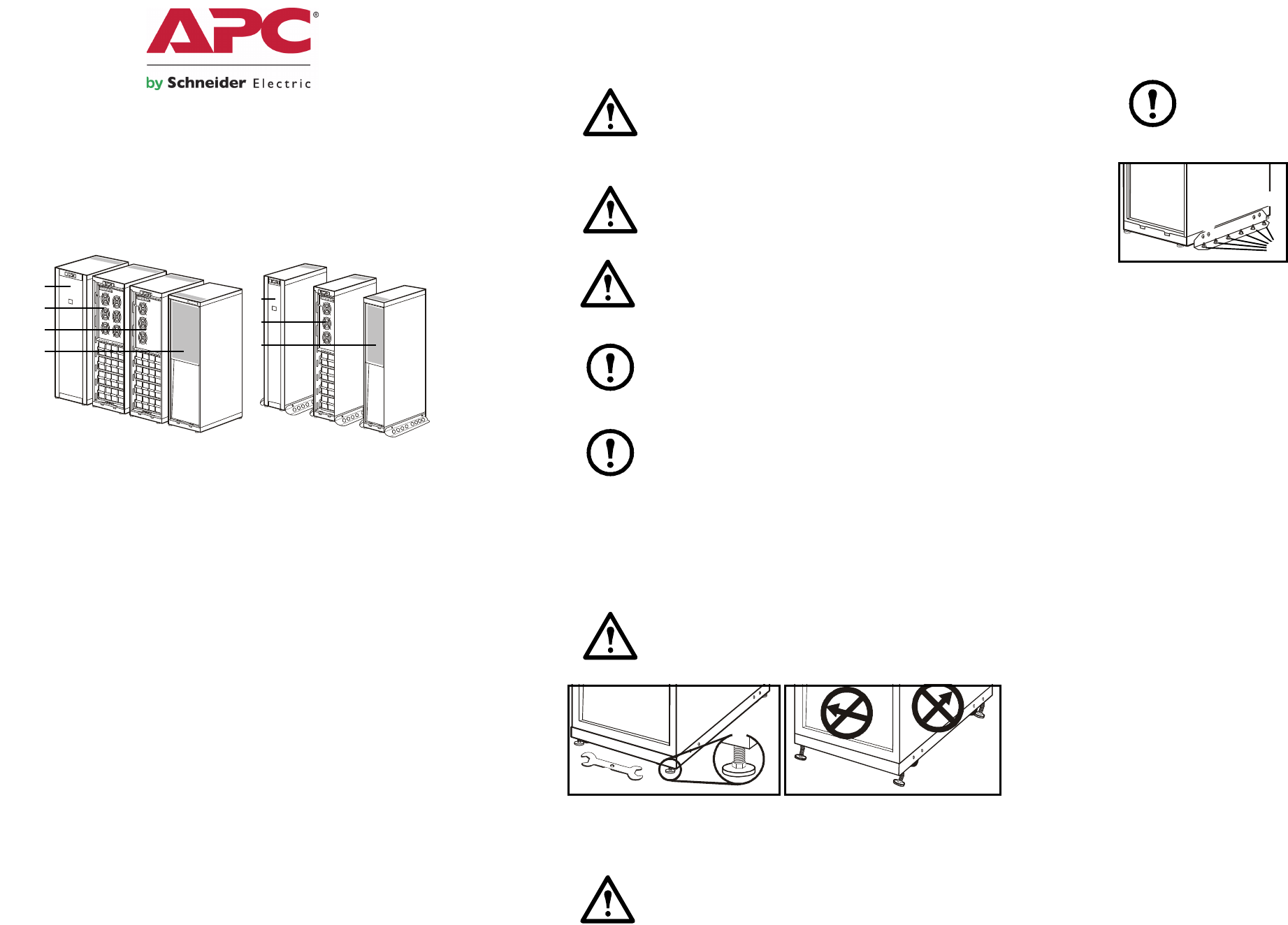
990-1986B-00110/2008*990-1986B-InstallationSmart-UPS® VT 10-40 kVA 380/400/415 V with batteries 10-40 kVA 20-40 kVA without front panel 10-15 kVA w
2Prepare for CablesBottom cable entry From the rear of the UPS, loosen the six M4 screws from the upper cover (the cable landing area) on the back an
3Connect the DC Battery Cables (if applicable) Connect battery cables BAT+, BAT÷, and N to the battery cable landings. Note: ONLY APC Smart-UPS VT
4Connect APC communication options Note: The cable routing of the power chute software and the temperature sensor is identical. Note: The temperature
5Battery inputBypass inputRecommended current protectionNote: AC input/output over-current protection and AC input/output disconnect must be provided
6ChecklistFor any optional equipment, refer to the product-specific manuals.Contact InformationFor local, country-specific centers: go to www.apc.com/
More documents for Uninterruptible power supplies (UPSs) APC Smart-UPS VT

Related products and manuals for Uninterruptible power supplies (UPSs) APC Smart-UPS VT
 (2 pages)
 (30 pages)
 (66 pages)
 (46 pages)
 (32 pages)
© 2020, manymanuals.com. All rights reserved. | 0.486 s |
 Manymanuals.com
 Manymanuals.de
 Manymanuals.fr
 Manymanuals.it
 Manymanuals.pl
 Manymanuals.cz
 Manymanuals.es
 Manymanuals-pt.com
Comments to this Manuals