APC SY20K40H Datasheet
Browse online or download Datasheet for Uninterruptible power supplies (UPSs) APC SY20K40H. APC Symmetra PX 20kW Scalable to 40kW N+1, 400V User Manual
- Page / 4
- Table of contents
- BOOKMARKS
Summary of Contents
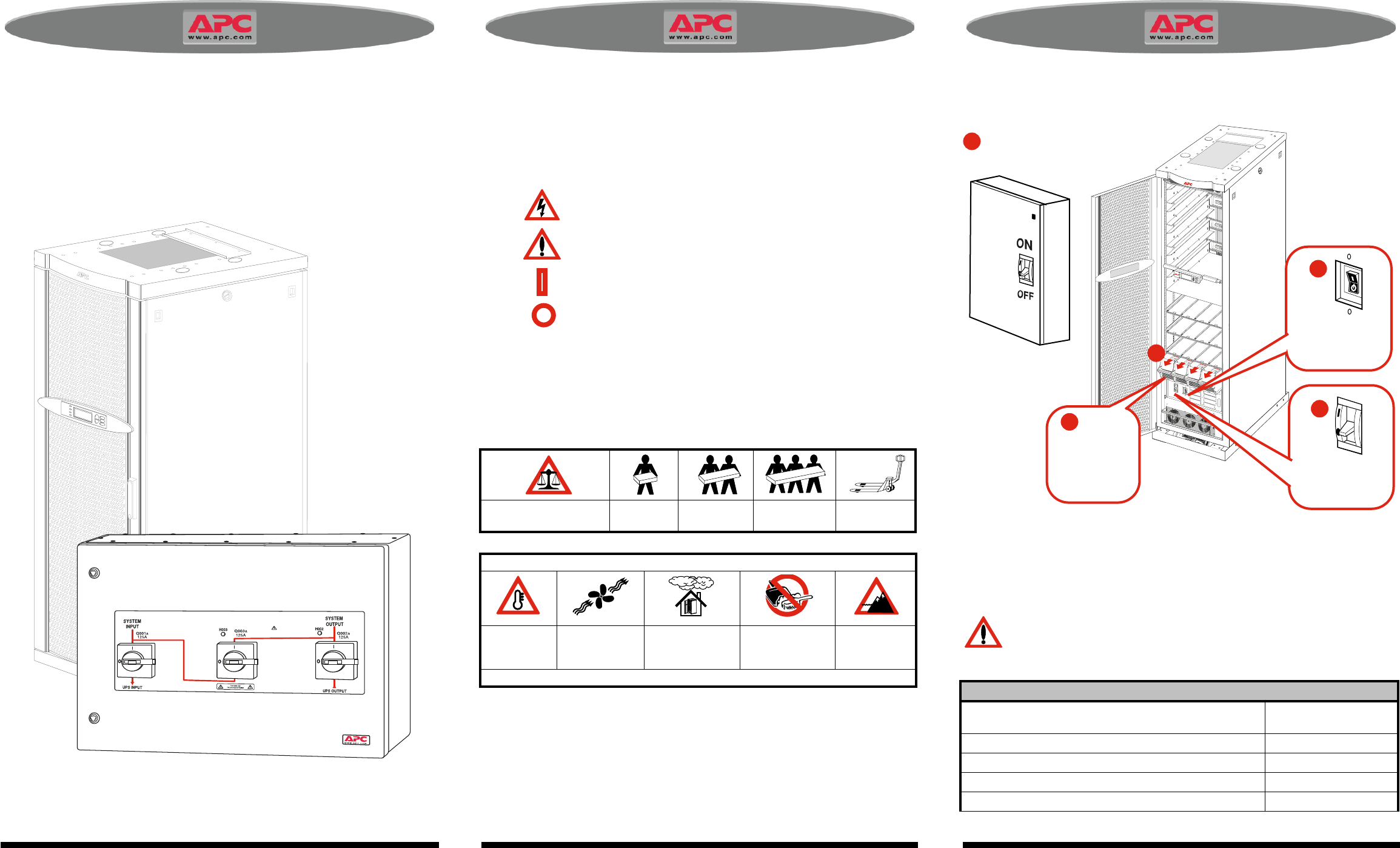
Maintenance Bypass Panel 60kW / Symmetra ® PX 10 - 40 kW, 400V 990-1277 Maintenance Bypass Panel 60kW / Symmetra ® PX 10 - 40 kW, 400V 990-1277
Maintenance Bypass Panel 60kW / Symmetra ® PX 10 - 40 kW, 400V 990-1277 Maintenance Bypass Panel 60kW / Symmetra ® PX 10 - 40 kW, 400V 990-1277
Maintenance Bypass Panel 60kW / Symmetra ® PX 10 - 40 kW, 400V 990-1277 Maintenance Bypass Panel 60kW / Symmetra ® PX 10 - 40 kW, 400V 990-1277
Maintenance Bypass Panel 60kW / Symmetra ® PX 10 - 40 kW, 400V 990-1277 Maintenance Bypass Panel 60kW / Symmetra ® PX 10 - 40 kW, 400V 990-1277
Related products and manuals for Uninterruptible power supplies (UPSs) APC SY20K40H
 (14 pages)
 (41 pages)
 (14 pages)
© 2020, manymanuals.com. All rights reserved. | 0.575 s |
 Manymanuals.com
 Manymanuals.de
 Manymanuals.fr
 Manymanuals.it
 Manymanuals.pl
 Manymanuals.cz
 Manymanuals.es
 Manymanuals-pt.com
Comments to this Manuals