Back-UPS ES 750
User’s Guide
1
2
3
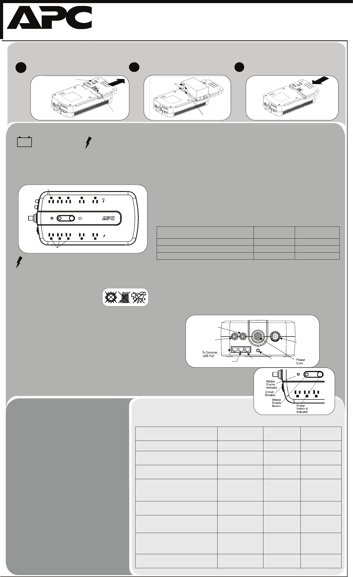
Connect Battery
Power On and Install
Software
Surge Protection
These outlets provide full-time protection from surges even if the Back-UPS ES
is switched OFF. Plug your printer, fax machine, scanner, or other peripherals
that do not need battery power into these outlets.
Place the Back-UPS ES to avoid:
- Direct sunlight
- Excessive heat
- Excessive humidity or contact with fluids
Plug the Back-UPS ES power cord directly into a wall outlet;
not a surge protector or power strip.
Connect Computer Cable
The supplied cable and software provide automatic file saving and shutdown of
the operating system in the case of a sustained power outage.
Connect the cable to the Data Port of the Back-UPS ES. Connect the other end
of the cable to the USB port on your computer. The software will automatically
find the USB Port of your computer.
Battery Back-up + Surge Protection
These outlets are powered whenever the Back-UPS ES is switched ON. During
a power outage or other utility problems (brownouts, over-voltages), these
outlets will be powered for a limited time by the Back-UPS ES. Plug your
computer, monitor, CD-ROM drive and one other data-sensitive device such as
an external disk or tape drive, or Home Phoneline Networking Association
(HPNA) device into these outlets.
Press the ON/OFF switch to power the unit ON.
A single short beep and the green “Power On” indicator
confirms the Back-UPS ES is on and ready to provide
protection.
The Back-UPS ES should charge for at least 16 hours to ensure
sufficient runtime. The unit is being charged whenever it is
connected to utility power, whether the unit is turned ON or
OFF.
If the red Building Wiring Fault indicator (located on the end
near the power cord) is lit, your building wiring presents a shock
hazard that should be corrected by a qualified electrician.
Install the PowerChute
®
Personal
Edition
software
Place the PowerChute Personal Edition CD-ROM into your
computer and follow the installation instructions on the screen.
w
w
w
.apc.com
®
The Back-UPS ES indicates operating status using a combination
of visual and audible indicators. Use the following table to identify
the status of the Back-UPS ES.
Status
Visual Indications
(Power On - Green)
(Replace Battery - Red) Audible Indication
Alarm Terminates
When
Power On - UPS is supplying conditioned utility
power to the load.
Power On LED - ON None Not applicable.
On Battery - UPS is supplying battery power to
load connected to Battery outlets.
Power On LED - ON (off
during beep)
Beeping 4 times
every 30 seconds
UPS transfers back to
Power On operation, or
when UPS is turned off.
Low Battery Warning - UPS is supplying battery
power to the load connected to the Battery outlets
and the battery is near exhaustion.
Power On LED - flashing
(every 1/2 second)
Rapid beeping
(every 1/2 second)
UPS transfers back to
normal operation, or
when UPS is turned off.
Replace Battery - The battery is disconnected.
The battery is in need of charging or is at the end
of its usual life and must be replaced.
Power On and Replace
Battery LEDs- Flashing
(alternating)
Replace Battery LED -
flashing
Constant tone
Constant tone
UPS is turned off with
the power switch.
Overload Shutdown - During On Battery
operation a battery power supplied outlet
overload was detected.
None Constant tone UPS turned off with the
power switch.
Overload Alarm - Online power exceeded
Back-UPS capacity.
Power On LED - ON Constant tone Equipment power plugs
are moved from Battery
Backup outlets to
Surge or Client outlets.
Sleep Mode - During On Battery operation the
battery power has been completely exhausted,
and the UPS is waiting for utility power to return
to normal.
None Beeping once every
4 seconds
Utility power is
restored, or if utility
power is not restored
within 32 seconds, or
the UPS is turned off.
Building Wiring Fault - Your building wiring
presents a shock hazard that should be corrected
by a licensed electrician.
Building Wiring Fault LED
(red) - ON
None UPS is unplugged, or is
plugged into a properly
wired outlet.
Status Indicators
®
See the Troubleshooting section for additional assistance.
For safety, the Back-UPS ES is shipped with one battery wire disconnected. The UPS will not operate until the wire is connected to the touch-safe battery terminal.
NOTE: Small sparks may occur during battery connection. This is normal.
Turn the Back-UPS ES over and press in the release tab.
Slide the plastic battery cover off the unit.
Insert the battery back into the compartment. Slide the
plastic battery cover back in place until the tab locks.
1
2
3
Connect Equipment
BatteryCover
Release Tab
Battery
Terminals
Connect the battery wire firmly to the battery terminal.
Idle peripheral devices (printer/scanners, speakers) continue to draw power when not in use. To conserve
power, the Back-UPS uses “master controlled outlets”. The Master outlet senses when the master device
(computer) that is plugged into the Master outlet is no longer drawing current, and automatically shuts off
power to the Controlled outlets. Pressing the MASTER ENABLE button for one second enables and disables
this feature. When enabled, the green MASTER ENABLE LED is lit (on). When it is disabled, the LED is not
lit (off). The Back-UPS ships with MASTER ENABLE activated. Note: Do not connect peripherals to the
Controlled Outlets if you want them to continue to run when your computer is turned off.
Threshold Programming
When the computer is turned off, the Master outlet shuts off power to the Controlled outlets. However, when
the computer goes into “hibernation (sleep) mode” the Master outlet may not properly recognize the reduced
power level. To ensure the Master outlet shuts off power to the Controlled outlets properly, the threshold set-
ting may need to be adjusted from the “default value”. If the peripherals plugged into the Controlled outlets
do not turn off when the computer goes into hibernation mode, first ensure the MASTER ENABLE LED is lit,
and if so, then perform the procedure provided below to switch the threshold setting to High. Conversely, if
the computer has an extremely low power level, it may require that the threshold setting be set to Low if the
Controlled outlets automatically shut off, even when the computer is running. The Back-UPS automatically
exits this mode in five seconds if no buttons are pushed, or no operations are run. The three threshold set-
tings that can be selected are summarized in the table below.
Perform the following steps to change the threshold settings:
1. Plug the Back-UPS into the utility power source; do not turn power on. The unit will be in standby mode
(no LEDs are lit).
2. Press and hold down the MASTER ENABLE button for 10 seconds, until all indicators flash to show it has
entered threshold programming mode.
3. When the MASTER ENABLE button is released, the LEDs that are illuminated indicate the current thresh-
old setting (Low, Medium or High).
4. Press the MASTER ENABLE button to select a different threshold setting.
Indicators Flashing Threshold Setting
Input Wattage Range
(Hibernation Mode)
1. Master Enable LED Low 10 Watts
2. Master Enable LED, On Line LED Medium (default) 25 Watts
3. Master Enable, On Line, Replace Battery LEDs High 60 Watts
Master/Controlled Outlets
Battery Wires
Connect Modem / Phone / DSL / Fax / 10/100Base-T / HPNA /
Cable Modem / CATV or DSS to Surge Protection
The Back-UPS protects a single line (2-wire) phone (including Digital Subscriber
Line - DSL), Home Phoneline Networking Association (HPNA) type equipment,
modem, 10/100Base-T Ethernet, or fax machines from surges when connected
through the UPS as shown in the drawing. The UPS also protects a cable
modem, CATV converter, or DSS receiver from surges when it is connected
through the UPS coaxial connectors as shown in the drawing.
Master
Controlled by Master
Battery Backup+
Surge Protection
Surge Protection
From Wall Jack
Dataline Output to
DSL Modem, Phone
Building Wiring
Fault Indicator
Cable Input
from Internet
Service
Cable Output
to Cable,
Modem, CATV
Converter,
or DSS Input
Circuit
Breaker
 (30 pages)
 (8 pages)
 (66 pages)
 (46 pages)
 (32 pages)
 Manymanuals.com
 Manymanuals.de
 Manymanuals.fr
 Manymanuals.it
 Manymanuals.pl
 Manymanuals.cz
 Manymanuals.es
 Manymanuals-pt.com
Comments to this Manuals