APC RAID Subsystem SCSI-SATA II Specifications Page 53
- Page / 94
- Table of contents
- BOOKMARKS
- Falcon II 1
- Installation and Hardware 1
- Reference Manual 1
- Copyright 2004 2
- Warnings and Certifications 3
- CB (Certified Worldwide) 4
- Table of Contents 4
- NSTALLATION 5
- Safety Precautions 7
- About This Manual 8
- Revision History 8
- Who should read this manual? 8
- Conventions 9
- Software and Firmware Updates 10
- This page is intentionally 11
- Chapter 1 12
- Introduction 12
- 1.1.2 Enclosure Chassis 13
- 1.1.2.3 Front Panel Overview 14
- 1.1.2.5 Rear Panel Overview 15
- 1.2.1 LCD Panel 16
- 1.2.2 Drive Trays 17
- WARNING! 17
- 1.2.6 DIMM Module 19
- 1.2.7 BBU 19
- 1.2.8 Power Supply Units 20
- 1.2.9 Cooling Modules 21
- 1.3 Subsystem Monitoring 22
- 1.3.4 Audible Alarms 23
- WARNING: 23
- 1.4.2 Components 23
- Chapter 1: Introduction 24
- Chapter 2 26
- Hardware Installation 26
- 2.3 Safety Precautions 27
- CAUTION! 28
- 2.5 Unpacking the Subsystem 30
- 2.6 Installation Overview 31
- 2.7 BBU Installation 31
- 2.7.3 Installation Procedure 32
- 2.8 Hard Drive Installation 34
- 2.9 Drive Tray Installation 37
- Chapter 3 40
- Subsystem Monitoring 40
- 3.2 Status Indicating LEDs 41
- 3.2.2 LCD Panel 42
- 3.2.3 Drive Tray LEDs 43
- 3.2.4 Controller Module LEDs 44
- 3.2.5 LAN Port LEDs 46
- 3.2.6 BBU Module LED 46
- 3.2.7 PSU LEDs 46
- 3.2.8 Cooling Module LEDs 47
- 3.3 Audible Alarm 48
- C Monitoring 49
- Chapter 4 50
- 4.2 Host Connection Topology 51
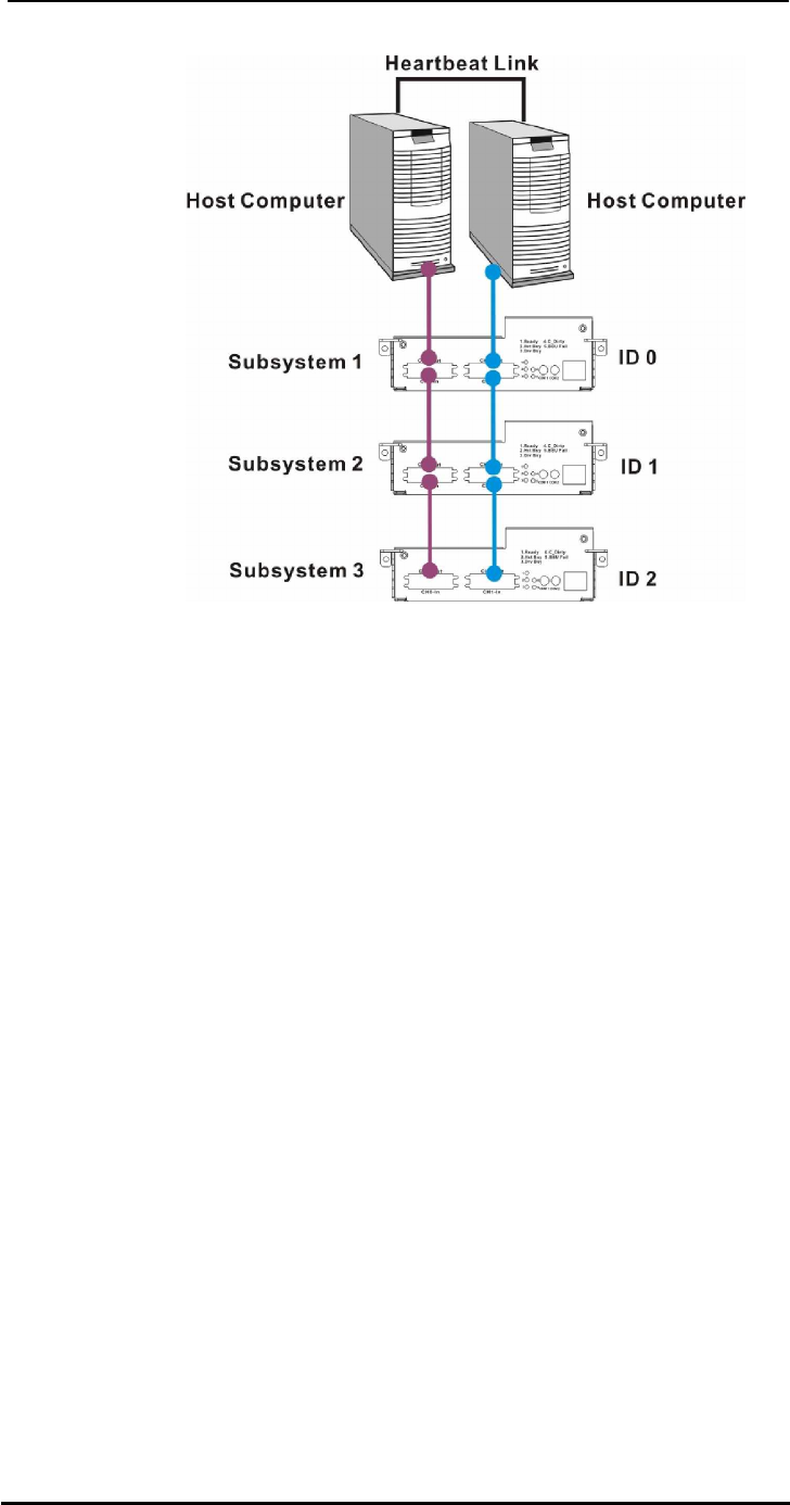
- 4.3 Daisy Chain 52
- 4.3.2 Daisy Chain Procedures 53
- 4.4 Power On 54
- 4.4.3 Power On Status Check 55
- 4.4.4 LCD Screen 56
- FALCON II 56
- 4.5 Power Off Procedure 57
- Chapter 5 58
- Subsystem Maintenance 58
- 5.3 DIMM Module Replacement 62
- White Clip White Clip 63
- 5.5.1 PSU Module Overview 65
- PSU Handle 67
- 5.6.1 Cooling Module Overview 68
- Side latches 69
- Silver Handle 69
- 5.7.2 Replacing a Hard Drive 71
- 5.8 Replacing a Dongle Kit 73
- Appendix A 74
- Uninterruptible Power Supply 74
- A.4.2 Set the Baud Rate 75
- A.4.3 Connect COM2 75
- A.5 Power On 76
- A.6 UPS Status Monitoring 76
- A.6.3 UPS Message Summary 78
- Appendix B 80
- Specifications 80
- Appendix B: Specifications 82
- Aliases for Target IDs 82
- Controller Specifications 83
- B.6 RAID Management 85
- Appendix C 87
- Spare Parts and Accessories 87
- C.2 Accessories 88
- Appendix D 89
- Pin Outs 89
- D.2 DB9 Audio Jack Pin Outs 90
- D.4 Null Modem 91
- D.5 Ethernet Port Pin Outs 92
- D.6 Main Power 92
- Index - 1 93
- Index - 2 94
Related products and manuals for Networking APC RAID Subsystem SCSI-SATA II
 (20 pages)
(32 pages)
(20 pages)
(32 pages)
 (32 pages)
(16 pages)
(85 pages)
(67 pages)
(32 pages)
(16 pages)
(85 pages)
(67 pages)
 (117 pages)
(32 pages)
(16 pages)
(9 pages)
(4 pages)
(117 pages)
(32 pages)
(16 pages)
(9 pages)
(4 pages)
© 2020, manymanuals.com. All rights reserved. | 3.499 s |
 Manymanuals.com
 Manymanuals.de
 Manymanuals.fr
 Manymanuals.it
 Manymanuals.pl
 Manymanuals.cz
 Manymanuals.es
 Manymanuals-pt.com
Comments to this Manuals