Back-UPS
™
325I/475I
User’s Manual
990-2114A 2/03
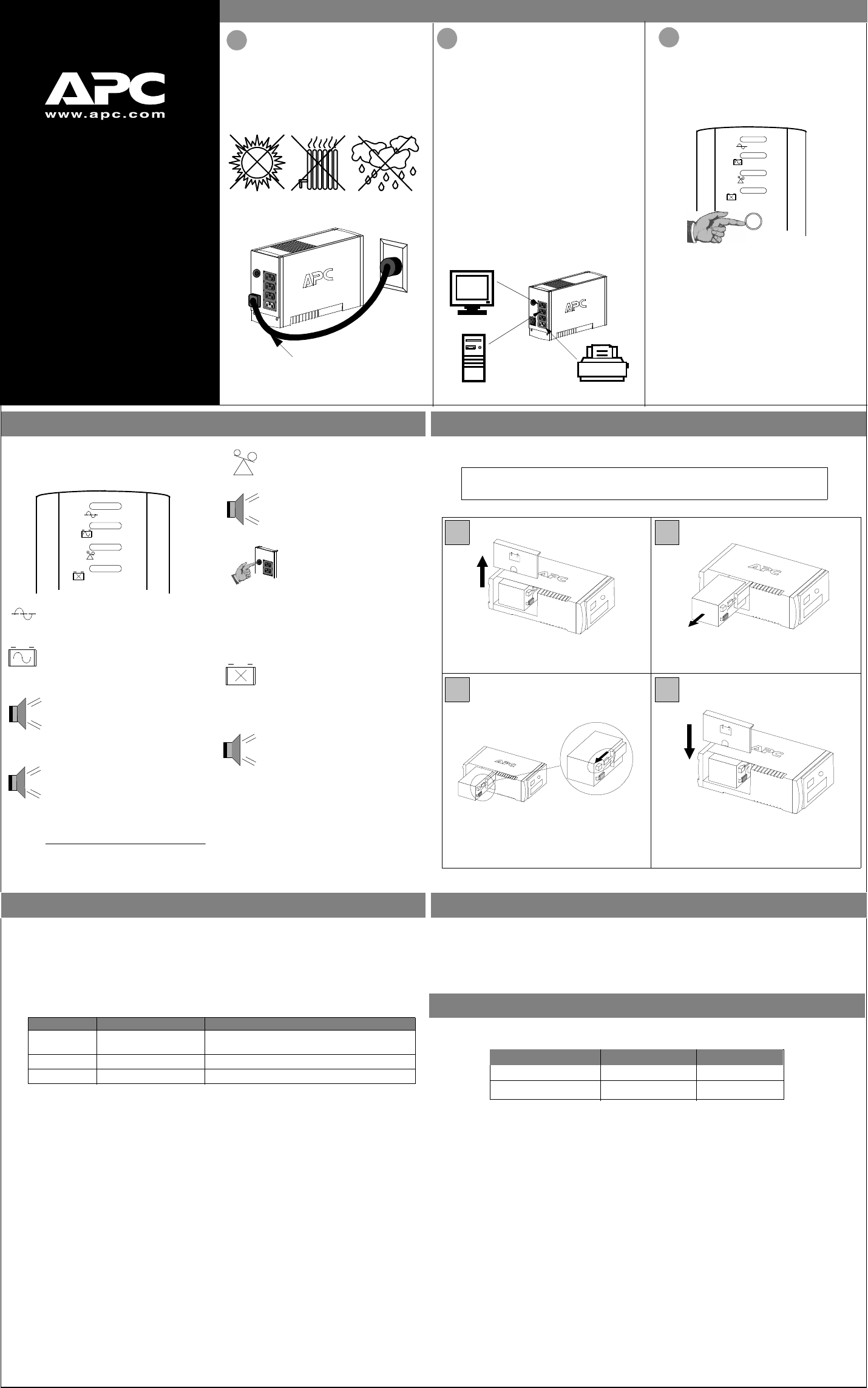
Installation
2
Connect Equipment
The rear panel of the Back-UPS consists of the
following elements:
Battery Back Up Outlets (qty. of 3). These
outlets provide battery back-up, surge protection,
and Electro-magnetic Interference (EMI) filtering.
In case of power outage, battery power is
automatically provided to these outlets. Power
(utility or battery) is not supplied to these outlets
when the Back-UPS is switched Off. Connect a
computer, monitor, and external disk or CD-ROM
drive to these outlets.
Surge Only Outlet. This outlet is always On
(when utility power is available) and is not
controlled by the On/Off switch. This outlet does
not provide power during a power outage. Connect
a printer, fax machine or scanner to this outlet.
Note: Allow the Back-UPS to charge for a full eight
hours prior to use.
Press the push-button on Back-UPS front panel.
Observe that the following events occur after pressing
and releasing the push-button:
• The green On-Line indicator flashes.
• The yellow On Battery indicator lights while the
Self-Test is being performed.
• When Self-Test has successfully completed, only
the green On Line indicator will be lit.
• If the internal battery is not connected, (see Step 1
above) the green On Line indicator and red
Replace Battery indicator will light. The Back-
UPS will also emit a chirping sound.
ON LINE
ON BATTERY
OVERLOAD
REPLACE BATTERY
There are four status indicators (lights) on the front
panel of the Back-UPS (On Line, On Battery,
Overload, and Replace Battery).
On Line (green) - is lit whenever utility
power is powering the Battery Backup
outlets.
ON LINE
ON BATTERY
OVERLOAD
REPLACE BATTERY
On Battery (yellow) - is lit whenever
the battery of the Back-UPS is powering
equipment connected to the Battery
Backup Outlets.
Four Beeps Every 30 Seconds - this
alarm is sounded whenever the Back-
UPS is running On Battery. Consider
saving work in progress.
Continuous Beeping - this alarm is
sounded whenever a low battery
condition is reached. Battery run-time is
very low. Promptly save any work in
progress and exit all open applications.
Shutdown the operating system,
computer and the Back-UPS.
Overload (red) - is lit whenever
power demand has exceeded the
capacity of the Back-UPS.
Continuous Tone - this alarm is
sounded whenever the Battery Backup
outlets are overloaded.
Circuit Breaker - the circuit
breaker button located on the rear
panel of the Back-UPS will stick
out if an overload condition forces
the Back-UPS to disconnect itself
from utility power. If the button
sticks out, disconnect non-
essential equipment. Reset the
circuit breaker by pushing the
button inward.
Status Indicators and Alarms
1
Placement / Power
3
Switch on the
Back-UPS
Avoid placing the Back-UPS in:
• Direct sunlight
• Excessive heat
• Excessive humidity or in contact with fluids
of any type
Plug the Back-UPS into a wall outlet, as shown.
• The Back-UPS charges the internal battery
any time it is connected to a wall outlet.
Your computer’s power cord.
Replace Battery (red) - is lit when-
ever the battery is near the end of its use-
ful life, or if the battery is not connected
(see above). A battery that is near the
end of its useful life has insufficient run-
time and should be replaced.
Chirps for 1 Minute Every 5 Hours -
this alarm is sounded whenever the
battery has failed the automatic
diagnostic test.
CS
®
to the Back-UPS
Replace the Internal Battery
To replace the internal battery, proceed as follows:
Note: Replacing the battery is a safe procedure. However, small sparks may occur
during the process. This is normal.
Slide the new battery into the battery compartment.
2
Pull the battery out, exposing the battery terminals
and wires. Disconnect the wires from the terminals.
Place the unit on its side. Slide the battery
compartment cover upward and off of the UPS.
1
3 4
Align the battery compartment cover with the grooves
Connect the battery wires to the terminals as follows: in the UPS. Slide the cover down until it locks.
Black wire to Ground (-) terminal
Red wire to Positive (+) terminal
APC and Back-UPS are registered trademarks of American Power Conversion
All other trademarks are property of their respective owners.
Transfer Voltage Adjustment (optional)
In situations where the Back-UPS or connected equipment appears too sensitive to input voltage, it may
be necessary to adjust the transfer voltage. This is a simple task requiring use of the front panel
pushbutton. To adjust the transfer voltage, proceed as follows:
1. Plug the Back-UPS into the utility power source. The Back-UPS will be in a Standby Mode (no
indicators lit).
2. Press the front panel pushbutton fully inward for 10 seconds. All indicators on the Back-UPS will
flash to acknowledge going into Programming Mode.
3. The Back-UPS will then indicate its current Lower Transfer Voltage, as shown in the following table.
4. To select 160 volts as the Lower Transfer Voltage, press the pushbutton until 1 indicator is flashing.
5. To select 180 volts as the Lower Transfer Voltage, press the pushbutton until 2 indicators are flashing.
6. To select 196 volts as the Lower Transfer Voltage, press the pushbutton until 3 indicators are flashing.
7. Once in Programming Mode, if the pushbutton is not pressed within 5 seconds, the Back-UPS will
exit the Programming Mode, and all indicators will extinguish.
Indicators Lit Lower Transfer Voltage Use When
1
2
3
160 VAC
180 VAC (factory default)
196 VAC
Back-UPS frequently goes On Battery due to
Normal power conditions exist.
Connected equipment is sensitive to low voltage.
low input voltage.
Back-UPS Storage
Before storing, charge the Back-UPS for at least eight hours. Store the Back-UPS covered and upright in a
cool, dry location. During storage, recharge the battery in accordance with the following table:
Please contact APC Technical Support to troubleshoot the unit before returning it to APC.
Storage Temperature Recharge Frequency Charging Duration
-5
o
to 30
o
C (23
o
to 86
o
F)
30
o
to 45
o
C (86
o
to 113
o
F)
Every 6 months
Every 3 months
8 hours
8 hours
The typical battery lifetime is 3-6 years (depending on the number of discharge cycles and operating
temperature). A replacement battery can be ordered over the phone from APC, or the battery can be ordered
on-line from the APC web site (see below, a valid credit card is required).
When ordering, please specify Battery Cartridge RBC2.
Order Replacement Battery
 (20 pages)
 (6 pages)

 (8 pages)
 Manymanuals.com
 Manymanuals.de
 Manymanuals.fr
 Manymanuals.it
 Manymanuals.pl
 Manymanuals.cz
 Manymanuals.es
 Manymanuals-pt.com
Comments to this Manuals